Adding Sonoff TX/T1 EU Wallswitches to ESPHome
For a while now if been annoyed with the old 1970’s surface mounted wall switches in my home. I mean they work but stylistically I didn’t like them much and I really wanted something more flush with the wall. After looking at some options I decided to go for the Sonoff TX series switches. They contain an ESP8266 which I am now a little more familiar with and should be easy to add to my growing Home Assistant setup and I really like the glass front. So I ordered a couple.
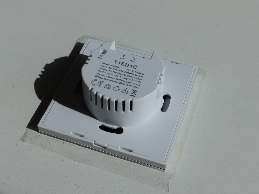
Taking it apart
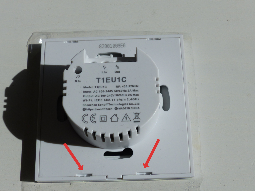
First I removed the glass front from the main electronics by inserting a flat head screwdriver into the marked slots and lightly pressed the bottom away from the housing.
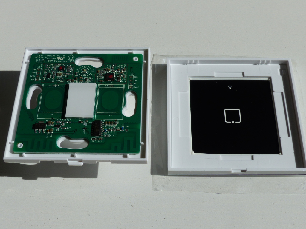
You would need to open the device the same way for normal installation. The guide I used for part of my changes shows you can also just put a flat head screwdriver in the slot in the middle and carfully twist the top off but I didn’t have much luck with that. Either way, you will be greeted by a green PCB.
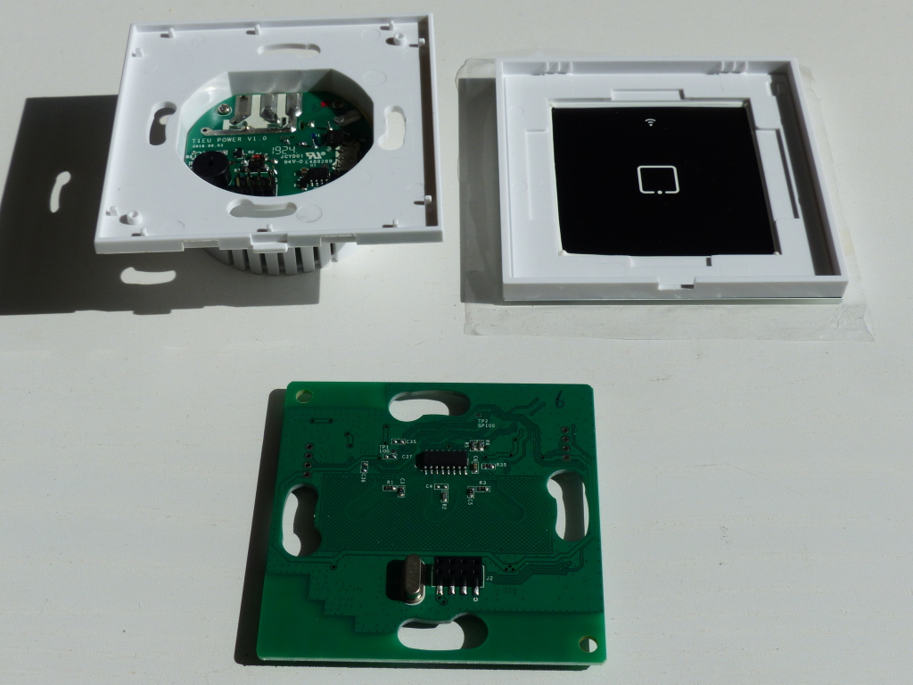
Next up, I lifted the PCB from the rest of the housing by putting one side of a plastic card under the side of the PCB and pressing down on the other side of the card. You can also do this with a flat head but look out for the traces on the PCB.
Now that the PCB with the ESP8266 chip is free of the rest we can continue with building the firmware, hooking it up and flashing it.
Building the firmware
The original article I followed uses some command-line stuff to create the base firmware and I’m sure I could figure that out, but since my ESPHome is integrated with Home Assistant already I opted to go the GUI route.
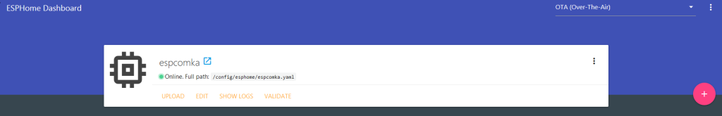
Then it is a question of filling out all the wizard steps, I didn’t worry about the Wifi Settings just yet as I will be changing the config later anyway.
Sometimes the clicking edit immediately after creation shows the config as 404 not found, but a refresh fixes that.
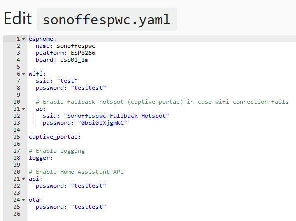
The configuration took me a little while, I had to look around a bit to figure out what everything did so I’ll go though what the parts of my config do.
This is the basic part of the config, is sets the name, the chiptype (esp8266) and size (1mb). It also contains the on_boot setting which tell the device to turn on the led on the touchpad, which I have on all the time, on boot. The blue_led_light it refers to will be set later in the config.
esphome:
  name: sonoffespwc
  platform: ESP8266
  board: esp01_1m
  on_boot:
    priority: -10
    then:
      - light.turn_on: blue_led_light
Next up is the WiFi settings with some bonus parts.
ssid is the name of your WiFi network of course and the password is … well you know. fast_connect makes the WiFi try to connect without first scanning all channels, it’s all basic stuff. Now the domain setting is there because I run my own DNS zone, so devices on my own network resolve the name of the ESP so I don’t have to mess with static IP’s. This device will be reachable on sonoffespwc.phiax.nl from inside the network but it will not exist outside of my network.
The ap and captive_portal parts are really cool too, if for whatever reason the ESP cannot connect to the WiFi, it will create its own WiFi network, that when connected to show you a page where you can scan and change the WiFi settings and restart.
ota password is needed for reflashing from the network or OverTheAir update.
logger will enable logging (what it says on the tin I guess 😉 ) and api password is the password Home Assistant will need to import and create the components.
wifi:
  ssid: 'WIFI-24'
  password: 'obviouslynotthis'
  fast_connect: on
  domain: .phiax.nl
  ap:
    ssid: "Espslaapka2 Fallback Hotspot"
    password: "obviouslynotthis"

captive_portal:

ota:
  password: "obviouslynotthis"

# Enable logging
logger:

# Enable Home Assistant API
api:
  password: "obviouslynotthis"
Now comes the part the took me a while to figure out. The binary_sensor component is the touchpad itself, it is a switch. So touching it has nothing to do with the relay toggling on or off. You could use the touchpad to switch on your oven but not the relay. Or you could not even use the touchpad and have the relay come on when you’ve got unread e-mail. You can really go nuts with it, but… We just want a light switch. So GPIO0 is the touchpad, we register it with the pin settings and tell it that if we touch it we want to toggle the relay (or turn on or off the light it connected to).
The output defines the led on the touchpad (GPIO13) and the actual relay part (GPIO12).
Lastly, the light component makes sure Home Assistant can make use of these outputs as lights. The source article registers them as switches, which do not work with Home Assistant groups like light.turn_off (service call to turn off every light) without having to do other changes.
binary_sensor:
  - platform: gpio
    pin:
      number: GPIO0
      mode: INPUT_PULLUP
      inverted: True
    name: "Touchpad"
    on_press:
      - light.toggle: light_switch
output:
  - platform: esp8266_pwm
    id: blue_led
    pin: GPIO13
    inverted: True
  - platform: gpio
    pin: GPIO12
    id: relay

light:
  - platform: monochromatic
    name: "Wifi LED"
    output: blue_led
    internal: true
    id: blue_led_light
  - platform: binary
    name: "Light"
    output: relay
    id: light_switch
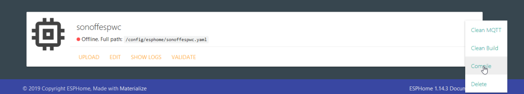
Anyway, after this I clicked save, then validate.
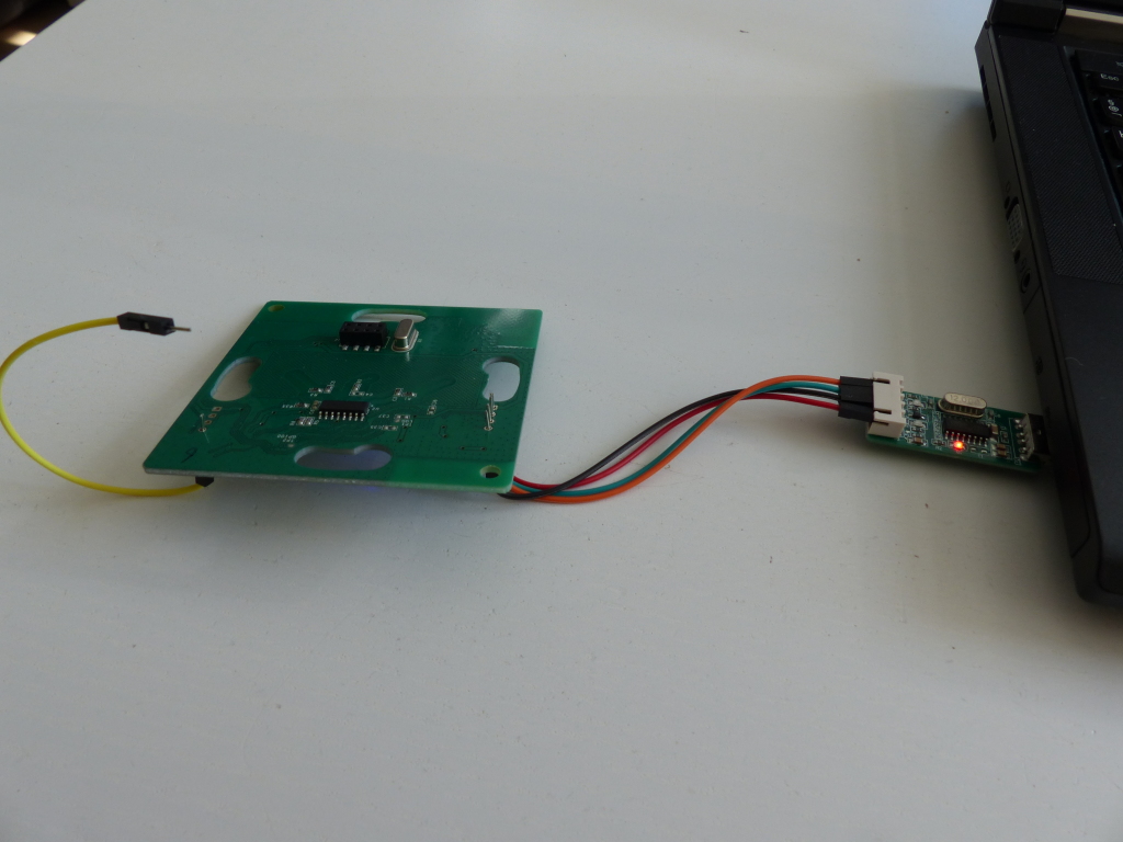
Connecting the UART
This part apparently used to be much easier because earlier version used to allow uploading custom firmware from the web interface. So you need a UART USB dongle for this that supports 3.3v (5v will fry the device).
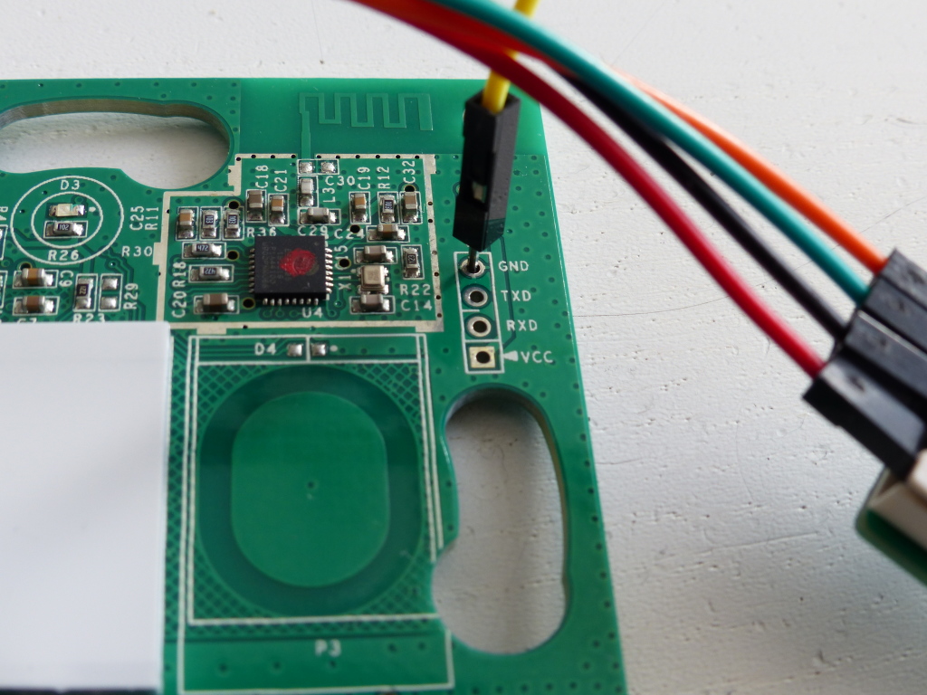
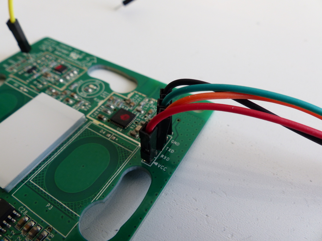
Luckily the process wasn’t really hard apart from needing the UART USB thingu which I did not have prior the this. But the folks who made this were nice enough to silkscreen where the wires would need to go (I moved the yellow wire later because I found another ground point and decided keeping all the UART pins next to each other made more sense)
This is where I noticed the biggest change in board revision from the source article, because I connected my yellow wire (moved from before) to the ground ready to hold it against GPIO0 pin of the chip to put the device in flash mode but…
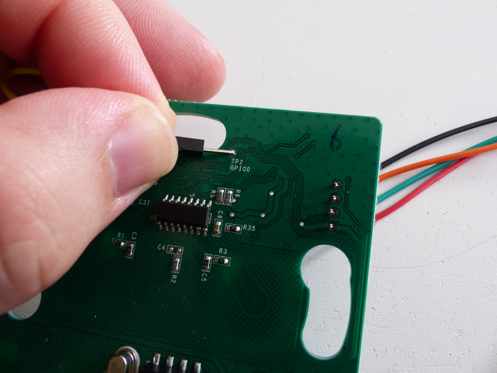
… my board revision comes with a extra pad to GPIO0. That takes the stress of accidentally hitting other pin away 🙂
Now, with the UART hooked up and the chip in flash mode (by holding the GPIO0 point to ground for about 10sec while connecting the USB side) it’s time to get flashing.
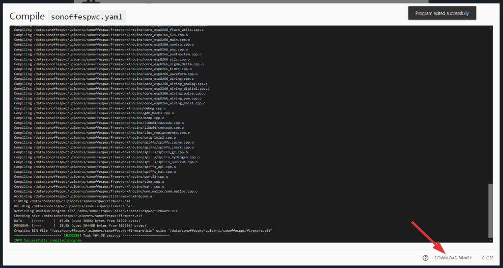
Time to flash
Flashing requires a python program called esptool (available here)
After getting that working the rest of the flashing part is just one line.
sudo python esptool.py --port /dev/ttyUSB0 write_flash 0x00000 ../sonoffespwc.bin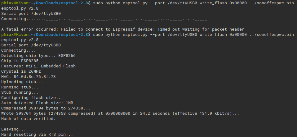
That was it, now all that’s left, install it into the wall.
Sources used
- https://esphome.io/devices/sonoff_t1_uk_3gang_v1.1.html
As a non-techy I have the feeling I can pull this of with your description. Thanks for the clear info.